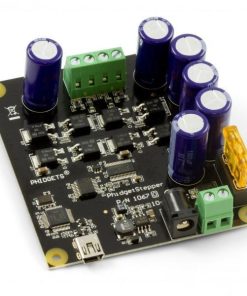
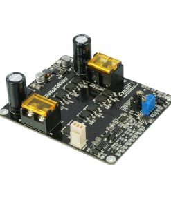
Phidget Motor Control 1-Motor – 1065_0B Phidgets
$ 119,00 $ 47,60
Phidget Motor Control 1-Motor – 1065_0B
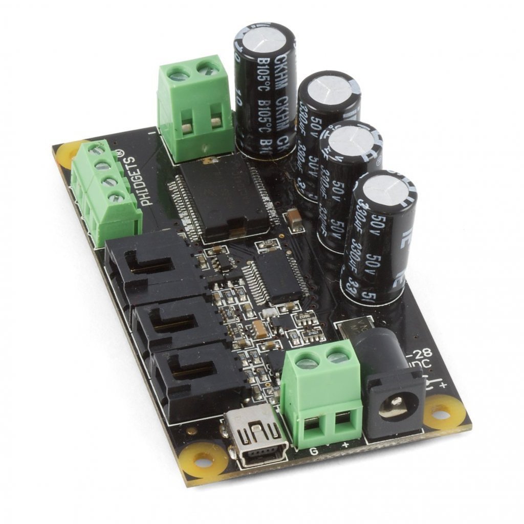
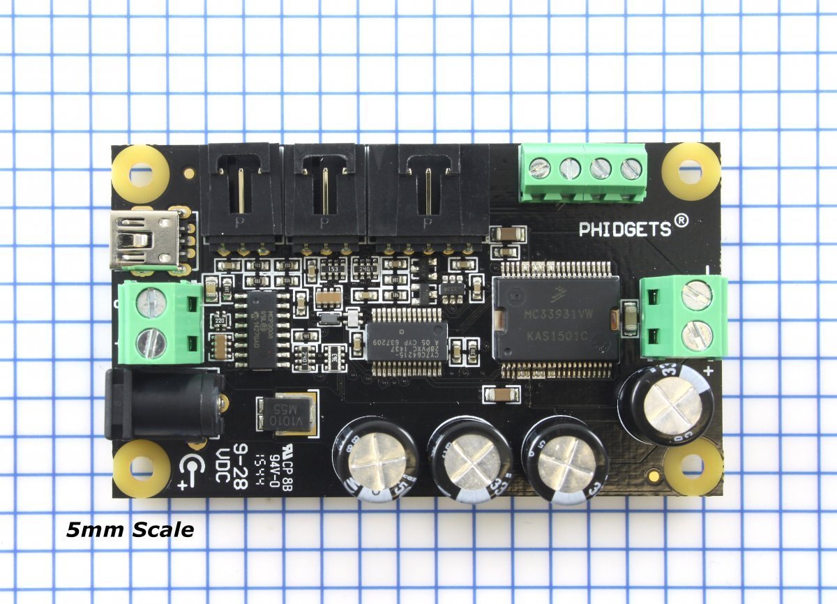
The 1065 lets you control the direction, velocity and acceleration of one DC Motor. The motor is powered by an external power supply (9 to 28VDC).
Brushed DC Motors are very simple to understand, but very difficult to control precisely. By applying a voltage, or pulsing a voltage rapidly, at the terminals of the motor, current flows through the motor, and it will begin rotating. Depending on the direction of the current, the motor will rotate clockwise or counterclockwise. The 1065 changes the effective voltage by changing the percentage of time the full supply voltage is applied to the motor. By switching the voltage very quickly (a technique called PWM), the controller is made smaller, more efficient, and cheaper.
Rough control of actual motor speed can be achieved automatically in software by using the Back EMF property, or current sensing.
Precise control of DC motors can be achieved by using encoders. You can implement control loops through software by using the data provided by the on-board digital inputs, analog inputs and encoder input. There is an event that triggers every 16 ms that returns the back-EMF value for the attached motor, which can be very useful for PID control. For more information, see the API in the User Guide.
The 1065 also provides over-current, over-voltage, and over-temperature protection to insure that the board and motor is not damaged.
Comes Packaged with
- A hardware mounting kit (4 nuts and bolts (M3), 4 plastic spacers)
Product Specifications
| Controller Properties | |
|---|---|
| API Object Name | MotorControl |
| Motor Type | DC Motor |
| Number of Motor Ports | 1 |
| Velocity Resolution | 0.39 % Duty Cycle |
| Acceleration Resolution | 24.5 % Duty Cycle/s |
| Acceleration Min | 24.5 % Duty Cycle/s |
| Acceleration Max | 6250 % Duty Cycle/s |
| Acceleration Time Min | 31.3 ms |
| Acceleration Time Max | 8.2 s |
| Board Properties | |
| Controlled By | USB |
| API Object Name | DCMotor |
| Encoder Interface | |
| Number of Encoder Inputs | 1 |
| Count Rate Max | 500000 cycles/s |
| Encoder Interface Resolution | x1 |
| Update Rate | 125 samples/s |
| Time Resolution | 0.33 ms |
| Encoder Input Low Voltage Max | 800 mV DC |
| Encoder Input High Voltage Min | 2.1 V DC |
| Encoder Pull-up Resistance | 2.4 kΩ |
| Electrical Properties | |
| Supply Voltage Min | 9 V DC |
| Supply Voltage Max | 28 V DC |
| Continuous Motor Current Max | 5 A |
| Overcurrent Trigger | 8 A |
| Current Consumption Min | 20 mA |
| Current Consumption Max | 100 mA |
| USB Speed | Full Speed |
| Physical Properties | |
| Recommended Wire Size (Power Terminal) | 12 – 24 AWG |
| Operating Temperature Min | 0 °C |
| Operating Temperature Max | 70 °C |
| Voltage Inputs | |
| Number of Voltage Inputs | 2 |
| Input Impedance | 900 kΩ |
| 5V Reference Error Max | 0.5 % |
| Update Rate | 125 samples/s |
| Digital Inputs | |
| Number of Digital Inputs | 2 |
| Pull-up Resistance | 15 kΩ |
| Low Voltage Max (True) | 800 mV DC |
| High Voltage Min (False) | 2.1 V DC |
| Low Voltage Trigger Length Min | 4 s |
| High Voltage Trigger Length Min | 16 s |
| Digital Input Voltage Max | ± 15 V DC |
| Digital Input Update Rate | 125 samples/s |
| Recommended Wire Size | 16 – 26 AWG |
Documents
- Programming Resources
- DC Motor and Controller Primer
- Motor Selection Guide
- Analog Input Primer
- Digital Input Primer
- Encoder Primer
- Mechanical Drawings
- Download 3D Step File
Library & Driver Downloads
- Windows libraries
- macOS libraries
- Linux libraries
- iOS libraries
Fast Shipping and Professional Packing
Through our long-term relationship in a long-standing partnership with UPS, FedEx, DHL and many other top global carriers we can provide a variety of shipping options. Our warehouse employees will pack every item to our exacting specifications. The goods you send us are checked thoroughly and secured properly prior to shipping. Everyday we deliver thousands of packages to customers across many countries. The fact that we're committed to becoming the biggest online retailer in the world is clear. Both Europe as well as the USA have warehouses and distribution centres.
Orders that contain more than one item are assigned processing times in accordance with the item.
We will inspect each and every one of the items ordered before shipping. Today, most orders will be shipped within 48 hours. The delivery time should be between 3-7 days.
Returns
The stock market is always changing. It's not entirely managed by us, since we have multiple organizations, such as the factory and our storage. Stock levels can fluctuate at any given time. Please understand it may happen that your order will be out of stock after the order is placed.
The policy is for 30 days. If you have passed 30 days in the past since you purchased, unfortunately we can't offer you a refund or exchange.
To be eligible for a refund, your item must be in good condition and in the same state that you received it. The item must be in the original packaging.
Related products
Motor Driver
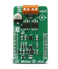
DC Motor 8 click – MikroElektronika Half-bridge MOSFET DC Motor Driver MikroElektronika
Motor Driver
Motor Driver
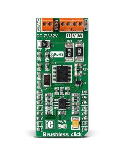
Brushless click – MikroElektronika 3-Phase Full-Wave Brushless DC Motor Driver MikroElektronika
Motor Driver
Motor Driver
Motor Driver
Motor Driver
Motor Driver
Stepper 7 click – MikroElektronika H-Bridge Bipolar Stepper Motor Driver MikroElektronika
Motor Driver
